- 5 Motor driver channels
- 2 EMG channels
- 5 Servo headers for tactile feedback
- 2 servo headers for thumb and wrist movement.
- Battery level display/clock face with RTC IC.
My supervisor had a license for Proteus PCB design tool so for the project I used it's design tool. To make this project properly available, I need to port the design over to Eagle or a similar open platform.

Due to the size/volume limits within the arm, I decided to go with a 4 stacked 2 layer boards. The top board is simply the display board and RTC circuit. For the display, i went with a clock face layout with 12 RGB LED's. The LED's I chose are those found in the Neopixel products from Adafruit. These addressable LEDs need only power ground and a single data in as they are daisy chained together. A 13th LED acts as a temperature sensor. The top corner of the PCB contains the RTC IC and crystal. The reverse side has the backup battery. A 6 pin header (Vcc, Gnd, LED, SCL, SDA, SW) connects the display to the next board.

The next board is the microcontroller board. I went with an ATMega 2560 for simplicity of programming since I was already familiar with the Arduino IDE. I started by copying necessary parts of the Arduino Mega 2560 schematic into the Proteus sorfware. After the ICSP and filtering had been sorted I broke out all the necessary pins. I went with a single row of headers along the top side of the board for all the ADC channels on the ATMega. 10 are needed but since there are 14 total, i decided to break them all out. Along the bottom edge of the board I put a double row of headers for all the drive control signals. Each channel takes two signals and an enable line is shared between each pair of channels. This makes 12 PWM control channels ( 6 channels) and 3 enable lines so a 8x2 header. 7 servo headers were placed along the right border of the board along with some large electrolytic caps. Finally, 8 GPIO pins were broken out on the board for any additional peripherals I could think of. A divider circuit to the controller board for battery level monitoring was also added. In hindsight, I should have placed a power-on led and general indicator LEDs on this board, along with a 5 pin header for a USB to FTDI dongle.
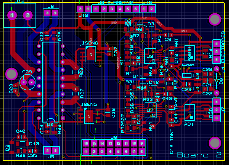
The next layer down contains one driver IC and the two EMG sensors. The EMG sensors are based on the EMG sensors of Advancer Technologies with the addition of a -5v supply to create a bipolar supply for the amps. A 5 pin header is used to connect to the electrodes ( 1 GND and 2 per channel) The 2 filtered, rectified and amplified signals are passed the the ADC header along the top edge of the board. The driver IC I chose is the L6205 by STMicroelectronics which is a dual channel full bridge driver capable of 2A per channel. Stall current for the chosen motors is 2.1A. I replicated the test circuit that's in the datasheet, including the bootstrap circuit. I added low side current shunts to the ground path of each driver with a fixed gain Allegro current amplifier. With this circuit drawn, it was just a case of copy and paste for the bottom board.

The PCB were manufactured by Seeedstudio and I had them back in hand within 10 days, which was great. Assembly was straightforward and everything was working fine except the EMG. after some probing with a multimeter and poring over the schematic, I realized that first of all, the -5v converter was going nuts and secondly, i'd grounded the -5v inputs on the op-amps meaning they weren't receiving the -5v supply. I tried fixing the issue with some angle wires and trace cutting but it still didn't work. I think with all the desoldering and resoldering damaged the traces beyond repair. With time running out, I bought a second dev board from Advancer (Had one for prototyping) and placed both of them under in the PCB with a separate -5V battery.
 |
| Boards back from Seeedstudio |
Next part i'll cover the final assembly and include some test footage.